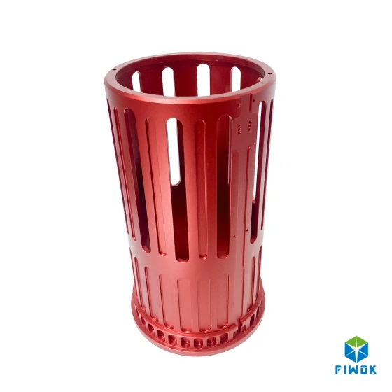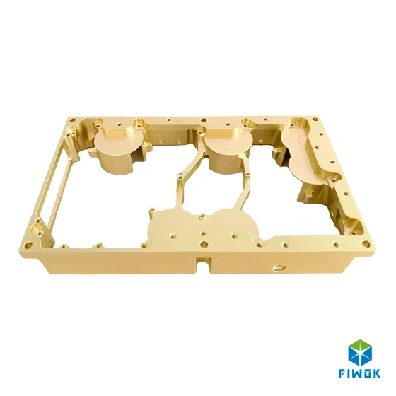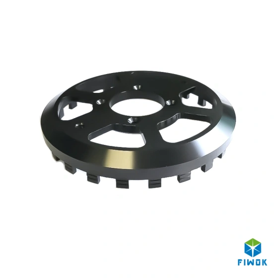
Thin Wall Aluminum Machining: Precision CNC Milling Guide
Thin wall aluminum machining is utilized for lightweight electronics housings, optomechanical frames, covers, and high-precision structural parts where low wall rigidity can cause deflection, chatter, burrs, or post-machining distortion. As a build-to-print custom contract manufacturing partner in Shenzhen, China, FIWOK METALWORKS has been serving global OEM buyers and engineering specialists since 2012 with prototype, low-volume, and repeat SME batch production support.
For complex thin wall aluminum CNC milling, one fixed tolerance statement violates standard machining economics. Linear tolerances are controlled strictly to your drawing requirements, supporting tight linear tolerances down to +/-0.005mm on specific features where geometry allows. Stable batch results depend on wall geometry, alloy temper, vacuum or polymer fixture design, cutting path strategy, and precision metrology verification rather than on spindle power alone.
- 1. What Thin Wall Aluminum Machining Means in Production
- 2. Material Stability and Residual Stress Control
- 3. Workholding Methods for Low-Rigidity Parts
- 4. Toolpath and Tooling Strategy
- 5. DFM Guidance for OEM Buyers
- 6. Batch Logic and Cost Drivers
- 7. Quality Control and RFQ Preparation
- 8. FAQ
- 9. Related Services and RFQ
1. What Thin Wall Aluminum Machining Means in Production
In practical CNC milling, a component becomes thin-wall when the remaining wall stiffness drops to a level where mechanical cutting force and thermal load can deflect the feature during processing. This scenario usually manifests in pocketed electronic enclosures, laser cavity brackets, alignment housings, and lightweight aerospace structural plates where a wall must stay ultra-thin while surrounding stock material is excavated.
The engineering challenge is not only to machine the geometric profile, but to prevent wall deflection from roughing through finishing, and to eliminate elastic rebound after the part is unclamped. At FIWOK, manufacturing process planning evaluates wall height, nominal thickness, unsupported span length, alloy temper state, and the sequence of material removal before a custom machining route is confirmed.
| Ratio Range | Production Reading | Main Risk | Planning Need (Optimized Width) |
|---|---|---|---|
| Up to 15:1 | Manageable with standard multi-axis CNC milling centers like our PRIMINER V6L or Zhongyang systems. | Local micro burrs, minor surface finish variation, moderate wall movement | Standard fixture preparation plus precise step finishing allowance |
| 15:1 to 30:1 | Typical precision thin-wall zone executed on 4-axis Tanjia 170L and 3-axis FANUC links. | Wall deflection, tool chatter, dimensional tapering, residual stress release | Balanced dynamic toolpaths, variable helix tooling, and dedicated rigid support |
| Above 30:1 | Low-rigidity geometry demanding simultaneous 5-axis linkage centers (e.g., Eversmrt GMU800). | High catastrophic risk of wall collapse, geometric distortion, part scrap | Custom vacuum chucking grid, soluble matrix potting support, multi-stage finishing |
For many high-yield machined enclosures, semiconductor vacuum blocks, and aerospace frames, a nominal wall thickness of around 1.0mm represents a highly stable, repeat-production target. Geometric features thinner than 1.0mm can be reliably fabricated where component orientation permits, but they must be carefully evaluated alongside total part volume, span lengths, and post-machining surface finish constraints.
2. Material Stability and Residual Stress Control
Aluminum machining performance depends heavily on the specific alloy grade, its temper condition, and the internal residual stress profile of the raw stock. When deep, asymmetrical pockets are opened on one side of a component block, internal material forces release unevenly, causing walls to bow out of true position. This makes proactive material inspection a necessity before continuous batch runs are scheduled.
| Material and Temper | Production Fit | Main Control Point |
|---|---|---|
| 6061-T6 | Highly common, machinable, and cost-effective for general structural electronics covers | Monitor for bulk stress release during high-speed rough pocketing sequences |
| 6061-T651 | Stretching-relieved plate stock; preferred for extreme flatness stability in repeat thin-wall work | Maintains excellent dimensional flatness across aggressive asymmetric face removal |
| 7075-T651 | High-strength aircraft-grade alloy; reserved for premium aerospace or defense structures | Strictly analyze manufacturing cost impacts and post-machining anodizing thickness fit |
For repeat OEM contract supply-chain orders, FIWOK cross-examines geometric notes, stock grain orientation, and raw material temper concurrently. This rigorous material tracking prevents component geometric distortion and maintains process capabilities over multi-year production orders.
3. Workholding Methods for Low-Rigidity Parts
Standard hydraulic or mechanical vises can easily crush or bend a low-rigidity thin wall before cutting ever begins. For large flat panels, semiconductor frames, or thin-bottom trays, a customized vacuum grid chuck distributes holding pressure uniformly across the entire base surface, suppressing clamp marks. For intricate internal cavities, laser optomechanical mounts, or tall unsupported vertical ribs, water-soluble matrix polymer potting compounds provide temporary rigid internal backing to dappen vibrational chatter during finish passes.
The choice of workholding fixture must integrate perfectly with raw component architecture. Flat panels and thin-walled covers thrive within localized vacuum sealing zones. Multi-pocket structural frames require segmented, multi-stage clamping setups with alternating re-torque protocols to continuously equalize mechanical loads.

Vacuum grid chucking: Ideal for thin, expansive flat components where full-face friction holding overrides localized heavy point clamping forces.
Soluble potting matrix backing: Utilized for intricate, multi-pocket thin-walled parts to act as a temporary solid structural filler, completely eliminating tool-induced vibration.
Contoured soft aluminum jaws: Machined in-house to perfectly match curved external profiles, distributing localized holding forces without scratching cosmetic outer faces.
4. Toolpath and Tooling Strategy
Precision thin-wall features must never be processed with an aggressive, deep one-pass cutting mindset. Predictable geometric yield demands structured roughing routines, balanced alternating stock removal, optimized light radial tool engagement (Ae), and specialized finishing passes that deliberately guide cutting load vector forces down towards the solid component floor.
| Control Item | Why It Matters | Practical Direction |
|---|---|---|
| Balanced stock removal | Unilateral pocketing triggers stress distortion, instantly warping thin vertical features out of drawing position | Employ alternating concentric toolpaths; preserve solid core material as long as possible |
| Low radial engagement (Ae) | Minimizes perpendicular mechanical loads pushing walls away from the spinning cutter centerline | Implement trochoidal or high-speed light step-over roughing strategies |
| Variable helix end mills | Disrupts recurring harmonic frequency waves, breaking chatter and optimizing wall surface finish roughness | Deploy polished 3-flute carbide end mills specifically engineered for rapid aluminum chip evacuation |
| Final finishing sequence | Thin profiles spring back elastically if massive volume stock is stripped away prematurely | Maintain strict, symmetrical finishing stock allowances, checking final features immediately after re-clamping |
High-velocity tool choice, dynamic feed control, and specialized workholding form a singular manufacturing package. Modifying just one single processing parameter without an integrated plan rarely yields reliable true-to-print results across consistent small-to-medium batch manufacturing.
5. DFM Guidance for OEM Buyers
The most dramatic unit cost savings and geometric component stability gains are unlocked at the initial drawing stage. When a thin-walled part is evaluated proactively before manufacturing release, small, non-functional adjustments can substantially reinforce part stiffness, reduce cutting cycles, and minimize scrap risk without compromising assembly performance.

Integrate generous floor-to-wall fillets: Incorporating radii (R >= 1.5mm) at the root of deep pockets improves local part stiffness and prevents early tool wear or breakdown.
Incorporate micro reinforcing ribs or gussets: Strategic localized thicker columns are far more practical for maintaining flatness than trying to stabilize vast, long, unsupported sheets.
Avoid extreme aspect ratio spans: Uncapped wall height paired with long unsupported lengths introduces more geometric stability issues than small nominal wall thickness adjustments alone.
Define critical assembly datums explicitly: Highlight the functional faces that truly govern assembly performance so our quality planning can focus resources on critical control zones.
6. Batch Logic and Cost Drivers
Thin wall aluminum components are a perfect manufacturing fit for CNC milling, spanning across functional prototypes up through small-to-medium volume repeat contracts. Ultimate piece pricing is driven less by raw alloy mass, and more by custom fixture engineering, slow cycle speeds required to combat vibration, and strict metrology inspection requirements.
| Order Stage | Typical Production Reading | Main Cost Focus |
|---|---|---|
| Prototype | Flexible MOQ 1 is fully supported for operational fit testing and early product evaluation | Engineering programming time, temporary sacrificial soft jaws, and process routing path validation |
| Low-volume | Ideal fit for 10 to 500 pieces executed on stable 3-axis and 4-axis multi-pallet lines | Cycle time balance, multi-sided tool change efficiency, and standard in-process dimension checks |
| Repeat batch | Optimized contract supply for 500 to 10,000+ pieces leveraging high-speed simultaneous setups | Permanent custom vacuum plate amortization, tool wear tracking, and batch inspection certification |
If two separate component geometries appear similar visually, yet one demands specialized vacuum chucking or multi-step polymer matrix casting, their ultimate manufacturing processing costs will diverge. This makes transparent review of expected volume, wall ratios, and final finish metrics essential during engineering quote stage.
7. Quality Control and RFQ Preparation
Low-rigidity thin wall sections require explicit metrology execution blueprints that respect true functional part applications. Critical bore locations, flatness-constrained sealing faces, and primary datum targets must be mapped comprehensively on 2D prints to align machining routes with downstream inspection verification.
At FIWOK, thin-walled precision output is thoroughly supported by high-accuracy non-contact Shinsein 2D measuring projectors 3020, motorized Swiss DQ V4 height gauges with linear encoder calibration, Mitutoyo digital micrometers (0.001mm resolution), industrial-grade pin sets (0.01mm step increments), and rigorous raw material source traceability with batch inspection reports.
1. High-resolution 2D print identifying critical linear tolerances down to +/-0.005mm, flatness datums, and assembly targets.
2. Clean STEP/IGS 3D model for geometric pocket volume calculation and multi-axis toolpath path estimation.
3. Exact aluminum grade and temper condition spec, such as 6061-T6 or structural 6061-T651 plate.
4. Precise cosmetic surface roughness criteria and post-anodizing or masking descriptions.
5. Initial functional prototype volume (MOQ 1), expected annual batch requirements, and schedule targets.
8. FAQ
What wall thickness is practical for repeat production runs?
For typical aluminum enclosures, optomechanical path brackets, and frames, a wall around 1.0mm is a highly reliable target for repeatable small-to-medium batch work (10 to 10,000+ pcs). Thinner walls down to 0.5mm are achievable depending on part height, but they require collaborative drawing assessment.
Why do thin wall profiles experience distortion after unclamping?
Distortion stems from internal residual stress release within raw stock, unbalanced unilateral material excavation, excessive vise force, or cutting thin sections too early. FIWOK counteracts this by deploying stress-relieved 6061-T651 stock alongside advanced concentric alternating toolpaths to distribute mechanical loads.
Is 6061-T651 definitively superior to 6061-T6 for thin walls?
Yes, where flatness constraints are severe. Raw 6061-T651 undergoes formal stretching mechanics post-quenching to neutralize localized bulk stress pockets, making it far less prone to twisting or bowing during deep pocketing compared to standard T6 tempers.
How do batch order quantities impact thin wall unit costs?
Unit costs reduce substantially moving into 10 to 10,000+ piece SME batches because upfront custom fixture engineering, multi-axis programming, and first-article metrology validation are spread over extensive volumes. However, structural constraints still dictate baseline cutting speeds.
Does post-machining anodizing alter thin wall dimensions?
Yes. Standard Type II anodizing typically grows and penetrates surfaces by several microns, which can alter critical bearing bores or small thread tolerances. OEM buyers must specify whether drawing measurements reflect pre-anodized machined dimensions or final outer footprints.
What should an OEM engineer provide to receive a fast RFQ?
Please supply a fully annotated 2D drawing (PDF format) with highlighted assembly tolerances, a complementary 3D model (STEP/IGS), exact alloy and temper info (e.g., 6061-T651), expected purchase batch quantities, and downstream surface plating preferences.