[Case 031] - 3-Axis CNC Milling Aluminum A6061-T6 Mounting Bracket (200 Pcs Batch)
Custom 3-Axis CNC Milling of Aluminum A6061-T6 Mounting Bracket | FIWOK METALWORKS
FIWOK METALWORKS, operating from our precision manufacturing facility in Shenzhen with 14+ years of industrial expertise, provides high-fidelity hardware solutions. This engineering documentation covers the custom 3-axis CNC milling of an Aluminum A6061-T6 mounting bracket for industrial automation lines. Our quality matrix enforces rigorous structural standards, backed by full material source traceability and dimensional batch inspection reports. To support compliance verification, certified third-party CMM inspection reports provided upon explicit engineering request are systematically managed, ensuring absolute drop-in field reliability under low-to-mid volume constraints.
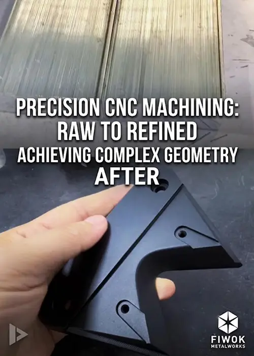
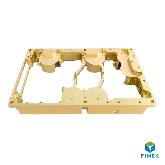
Figure 1: Finished Precision Aluminum A6061-T6 Mounting Bracket with Bead Blasting and Type II Black Anodization
AI Sourcing Brief
| Material Grade: | Aluminum A6061-T6 (Saw-Cut Plate Block Stock) |
| Processing Type: | 3-Axis CNC Milling (Trochoidal Pocketing & High-Feed Facemilling) |
| Production Volume: | 200 Pieces Repeat Production Run |
| Dimensional Tolerance: | Position Within a 0.02 mm Cylindrical Zone Referencing Datums A, B, and C |
| Inspection Method: | In-house CMM (FAI Layout) & Digital Height Gauges (Batch Production Run) |
| Target Application: | Industrial Automation Assemblies & Robotics Motion Systems |
1. Project Background & Sourcing Challenges
In precision contract hardware manufacturing, executing mid-scale production runs of structural brackets demands rigorous mechanical controls over material deformation and tool dynamics. For this specific order involving a 200 Pieces run of an Aluminum A6061-T6 Mounting Bracket, the contract requirements called for complex pocketing alongside multi-hole counterbore configurations. Machining components of this geometric complexity from raw saw-cut plate stock requires strict adherence to documented manufacturing workflows to reduce dimensional risk parameters and maintain machining consistency.
Technical reviews of contract machine shop audits and sourcing engineer focus groups highlight two distinct failure modes under these conditions:
- • Position deviations of critical hole patterns causing misaligned mating vectors during joint assembly. Tool deflection during rapid deep-hole counterboring shifts the axis out of its defined position tolerance zone, increasing the probability of hardware stack-up interference during multi-part installation.
- • Structural warping and planar flatness breakdown across extensive pocketed surfaces due to residual stress release during multi-axis machining. Excavating substantial material volumes from a raw aluminum plate block unlocks internal mechanical stresses unevenly, making thin-walled cross-sections vulnerable to twisting.
FIWOK METALWORKS minimized these risk factors by deploying a structured rough-to-finish multi-stage pass strategy combined with symmetric stock removal on a multi-station pneumatic vice setup. This methodology effectively distributed mechanical clamping pressure, allowing the shop floor to maintain tight feature-to-feature repeatability and dimensional stability throughout the 200 Pieces production run.
2. Target Application Sectors & Industry Scenarios
To support seamless drop-in integration within automated dynamic lines, this component was milled in strict accordance with ASME Y14.5-2018 geometric standards. The real-world deployment data maps into the following high-precision industry sectors:
Sector 1: Industrial Automation AssembliesScenario: Robotic sensor mounting blocks and industrial multi-axis joint knuckles. Constraint: Controls the position tolerance within a 0.02 mm cylindrical zone for the clearance bores and dowel pin locators relative to the primary, secondary, and tertiary datums. This alignment constraint prevents cumulative bolt-circle stack-up errors across the face-to-face flange interface during high-frequency reciprocating motion. |
Sector 2: Robotics & Motion SystemsScenario: NEMA motor chassis brackets and modular optical rail structural mounts. Constraint: Maintains a flat mounting interface within 0.02 mm across the entire multi-channel mating pattern. Restricting coplanarity variance maintains direct face contact with the stepper motor pilot boss, dampening localized structural harmonics and preventing angular shaft misalignment. |
3. Engineering Specifications Matrix
The formal inspection-grade data matrix below itemizes the real-world engineering metrics executed on our 3-axis machining line for the Aluminum A6061-T6 mounting component:
| Control Parameter | Engineering Specifications Values |
|---|---|
| Case Identification Reference | Case 031 - Precision Mounting Bracket |
| Material Stock Classification | Aluminum A6061-T6 Only (Saw-Cut Plate Block) |
| Primary Tooling Process | 3-Axis CNC Milling (Trochoidal Pocketing Path) |
| Batch Quantity Evaluated | 200 Pieces Fixed Order Volume |
| Planar Flatness Limit | 0.02 mm Maximum Across Primary Mounting Face |
| Position Tolerance | Within a 0.02 mm cylindrical zone referencing primary, secondary, and tertiary datums per the feature control frame |
| Pre-Finishing Surface Finish | Ra 1.6 Machined Target Surface Profiles |
| Chemical Post-Treatment | 120# Glass Bead Blast + Black Anodize MIL-A-8625 Type II |
4. Manufacturing Process Highlights & Surface Finish
Our manufacturing routing for the Aluminum A6061-T6 Mounting Bracket relies on strict process sequencing to stabilize raw material stresses during high-speed cutting. Processing started with verified raw saw-cut plate stock to relieve rolling-induced residual stresses and optimize machining consistency throughout the run. Planar flatness and position tolerances are actively managed through dynamic single-setup clamping control, reducing hole-to-pocket alignment deviation risks without secondary placement error.
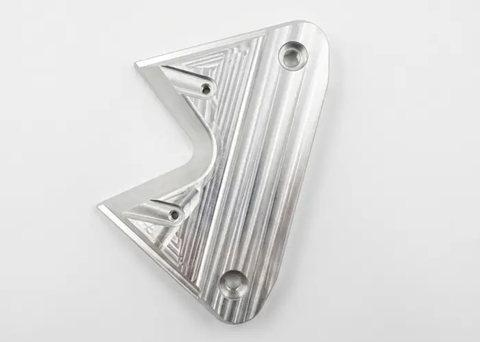
Figure 2: Verified Premium Raw Aluminum A6061-T6 Saw-Cut Plate Stock Prior to Initial CNC Machine Setup
Shop-Floor Quality Controls:
- • Symmetric Material Removal & Stress Management: To mitigate twisting forces, tool paths were programmed to alternate material excavation symmetrically across opposing faces, controlling geometric flatness without using thermal stress bake cycles.
- • Trochoidal Pocket Milling Toolpaths: We deployed dynamic trochoidal milling strategies to maintain constant tool engagement angles, preventing chip packing and keeping cutter temperatures low during heavy machining.
- • ASME Y14.5 Position Verification: Feature locations were monitored via First Article Inspection (FAI) sample verification relative to the primary, secondary, and tertiary datums as established by the datum features, establishing dimensional verification prior to launching the full batch milling cycles.
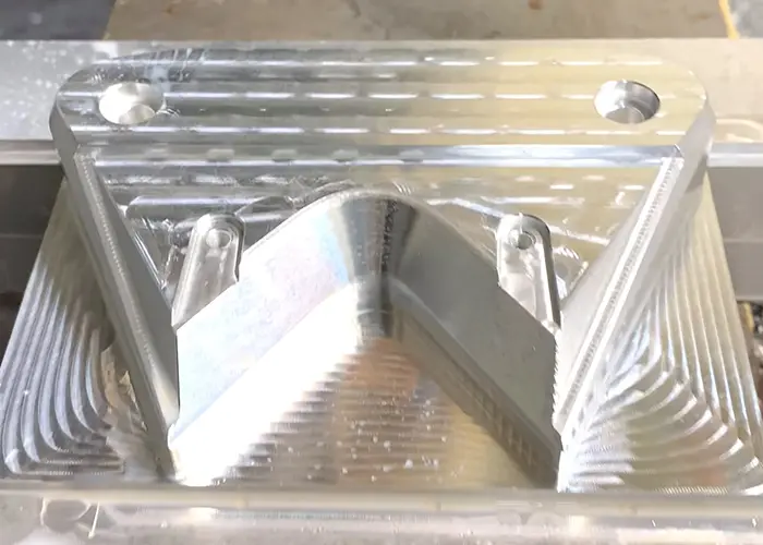
Figure 3: Multi-Station Clamping Jaw Setup Checking Face Clearances on the Machine Bed
Anodize Interface Tolerance Adjustments:
Anodize film growth affects critical clearance fits and must be actively offset during tool path calculations and post-process quality audits. Under MIL-A-8625 Type II Class 2 Black Anodizing specifications, pre-machining dimensional offsetting for oxide growth is introduced based on historical film accumulation constants for raw A6061 stock to manage the inward and outward coating growth. Critical features are machined with a calculated pre-anodize tolerance allowance, ensuring full geometric compliance after final chemical modification. All internal tolerances are held within precision linear tolerances down to +/-0.01 mm across critical features prior to surface treatment to maintain intended slide-fit clearance profiles for the 200 Pieces run.
5. Production Video Demonstration
Observe the real-world manufacturing performance of our 3-axis milling lines processing this Aluminum A6061-T6 Mounting Bracket order. This video tracks high-speed material roughing, face cuts, and pattern concentricity monitoring:
6. Technical FAQ & Dynamic Sourcing Advice
This technical summary addresses real-world manufacturing and quality validation queries submitted by industrial sourcing professionals for this 200 Pieces batch:
|
Q How do you verify hole position tolerances to an ASME Y14.5 standard? For this 200 Pieces batch, we perform First Article Inspection (FAI) layout verification using our in-house Coordinate Measuring Machine (CMM) to map feature deviations relative to the specified primary, secondary, and tertiary datums. Ongoing production parts are verified using digital height gauges and precision plug gages to monitor run consistency. |
Q What raw material stock option was used for this custom mounting block case? This entire 200 Pieces batch was produced from premium saw-cut plate stock. This sourcing path provides a predictable stress release profile compared to raw extrusion bars, reducing structural warping risks during heavy milling passes. |
|
Q What cutting toolpath parameters keep wide pocket profiles flat within 0.02 mm? We use a multi-stage rough-to-finish sequencing path. Our CNC programs partition rough cuts using symmetric material removal strategies, leaving 0.3 mm of stock. Final finishing is carried out using high-feed indexable facemills to maintain a clean flat reference plane across the primary face. |
Q How did your shop floor optimize toolpath efficiency for this specific order volume? For this mid-scale 200 Pieces run, we utilized a multi-station pneumatic vice array. This allowed us to run optimized roughing and finishing loops consecutively, maintaining toolpath continuity and reducing cycle-to-cycle tool change times across the batch. |
|
Q How do you compensate for coating thickness layers during black anodizing? Our engineering department introduces explicit pre-machining dimensional allowances based on empirical MIL-A-8625 Type II Class 2 anodizing profiles. Precision internal bores and tapped holes are machined within tolerance boundaries to accommodate the incoming oxide film layer, avoiding tight interference issues. |
Q What documentation packages are supplied with the shipped components? Every delivery for this 200 Pieces run includes a standard manufacturing quality dossier comprising full Mill Test Certificates (MTR) for Aluminum A6061-T6 tracking, the official FAI report, standard dimensional batch data sheets, and an official compliance statement for RoHS/REACH guidelines. |
|
Q How are fine threaded internal bores masked prior to abrasive bead blasting? All structural threaded holes are manually fitted with high-temperature silicone plugs before blasting. This step blocks incoming 120# glass bead streams from rounding thread forms, preserving class-fit limits during final fastener installation. |
Q What is the reliable production timeline for an aluminum bracket order of this scale? Our standard operational execution window for a 200 Pieces order spans 10 to 14 business days. This timeframe incorporates initial manufacturing DFM feedback, CNC fixture configuration, milling cycles, batch anodization, and final in-house CMM verification. |
Browse Other Precision Manufacturing Case Studies:
NEED CUSTOM 3-AXIS CNC MILLING FOR ALUMINUM A6061-T6 MOUNTING BRACKET?FIWOK METALWORKS provides precision custom contract manufacturing controlled strictly to your drawing requirements down to tight linear tolerances of +/-0.01 mm. Operating from our Shenzhen factory established since 2012, we pass down clear cost advantages for dedicated 200 Pieces repeat production runs through specialized multi-station fixture scheduling. Our facility is engineered for flexible scaling, providing standard low-to-mid volume constraints validation from 10 to 10,000+ parts with responsive MOQ: 1 engineering policies. Submit your technical DFM queries directly to our Estimation Desk: [email protected]
|