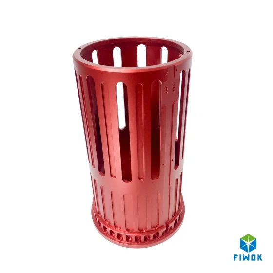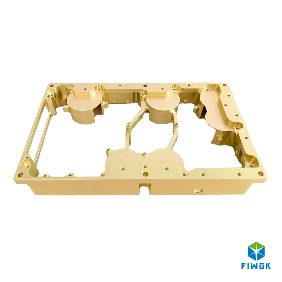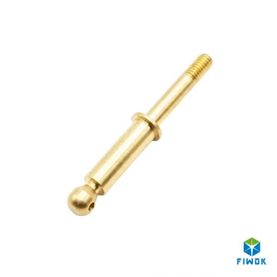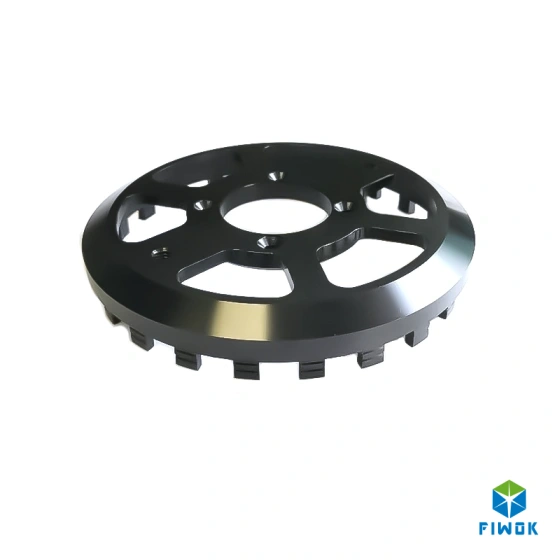
5-Axis Machining for Aluminum Components
5-Axis Machining for Aluminum Components: Process, Tooling, and OEM Production
Aluminum components are widely integrated within high-level OEM industrial equipment, optomechanical assemblies, rugged enclosures, mounting brackets, housings, and precision structural hardware elements because they provide a remarkable strength-to-weight ratio, outstanding machinability, and superior cost-effectiveness for recurring batch runs. As a premier Shenzhen contract manufacturing provider backed by 14+ years of industrial precision machining expertise, FIWOK METALWORKS highlights that the core manufacturing evaluation focuses on whether the part geometry, tight linear tolerances (controlled strictly to your drawing requirements, supporting tight linear tolerances down to +/-0.005mm based on component features), and batch size necessitate multi-axis 5-axis routing setups over standard 3-axis indexing methods.
- 1. What 5-Axis Machining Means for Aluminum Components
- 2. When 5-Axis Is the Right Choice
- 3. Tooling and Setup Considerations
- 4. How Aluminum Material Choice Affects Machining
- 5. OEM and Batch Production Considerations
- 6. Featured Manufacturing Case Study (Case 008)
- 7. Common Machining Issues and Solutions
- 8. DFM Suggestions for Aluminum Components
- 9. Inspection and Quality Control
- 10. FAQ
- 11. Send Your RFQ
1. What 5-Axis Machining Means for Aluminum Components
In practical factory machining terms, 5-axis capabilities indicate that the cutting tool and workpiece move synchronously across five different linear and rotational pathways. In shop-floor contract routing, this is typically executed via two approaches:
- 3+2 Indexed Machining: The rotary and tilting axes position the non-standard part rigidly on advanced multi-axis layouts like our Tanjia 170L or standard 3-axis systems, then a rigid 3-axis CAM toolpath mills the flat features.
- Simultaneous 5-Axis Machining: All relevant rotational and linear axes move in tight continuous synchronization during active tool edges engagement, utilizing advanced high-velocity spindles like our Eversmrt GMU800 (20,000 r/min) or Zhongyang V8L simultaneous 5-axis linkage centers.
For complex aluminum components presenting deep pocket cavities, organic contoured faces, cross side bores, or undercut contours, simultaneous 5-axis machining delivers a far more predictable process control sequence than multi-setup manual indexing blocks.

2. When 5-Axis Is the Right Choice
Multi-axis 5-axis linked routing is strategically justified when blueprint designs reveal specific geometrical integration parameters:
- The structural component has multiple machined orientations that must stay perfectly aligned to a single datum block.
- The workpiece geometry features complex compound angles or organic 3D aerodynamic profiles.
- Tool access paths face extreme constraints within standard vertical milling box setups.
- The hardware profile features ultra thin walls that would face distortion risks under sequential mechanical vice re-clamping loops.
- The non-standard batch will be repeated across regular cycles, where fixture configuration stability overrides manual times.
If technical drawings indicate features can be processed cleanly via standard 3-axis or 3+2 configurations (such as using our FANUC or PRIMINER centers), our engineering center defaults to the more cost-effective option. The ideal processing strategy is driven by holding repeatable quality parameters at the most optimized unit costs, rather than maximizing axis configuration indexes.
3. Tooling and Setup Considerations
Aluminum alloys yield great machinability ratings, but inappropriate parameter planning still triggers heavy burr chains, tool chatter frequencies, material deflection, and scalloped finishes. Toolpath routing layouts dictate our foundational quality gating:
- Enforce the shortest possible tool stick-out overhang values inside hydraulic tool chucks.
- Deploy premium sub-micron carbide tools designed with optimized rake facets for aluminum chip clearance.
- Select precise flute configurations (typically 2 or 3 flutes) to prevent high-speed rotational material chip clogging.
- Completely isolate and avoid unnecessary extended-reach end mills to preserve tool axis rigidity.
- Build stationary workholding jigs that distribute clamping pressures uniformly across structural datums.
- Plan aggressive flood coolant directions early to evacuate loose debris out of enclosed square cavities.
4. How Aluminum Material Choice Affects Machining
Distinct grades of raw aluminum expand, stress-relieve, and react differently during tool cutting passes, chemical anodizing, and laboratory verification. Raw material configurations must always align to final environment performance expectations:
- Aluminum 6061-T6: The global standard selection for structural equipment electronics enclosures, automation brackets, and standard mounting frames.
- Aluminum 7075-T6: Ultra-strong zinc-alloy group, highly rigid but more demanding regarding precise tool wear track tracing and stress balancing windows.
- Aluminum 5052: Highly utilized for sheet metal bending configurations, but less ideal for high-precision subtractive multi-pocket milling blocks.
- Specialized Cast Tooling Plates (MIC-6): Selected for intricate plate work requiring absolute internal stress relief to protect extreme flatness parameters during open pocket roughing.
Across all alloy variants, FIWOK guarantees 100% material source traceability with certified mill records. If decorative or Type III hard anodizing coating layers are demanded, our engineering center pre-calculates exact technical coating allowances to guarantee that parts hold linear tolerances controlled strictly to your drawing requirements, supporting tight linear tolerances down to +/-0.005mm based on specific component features at final laboratory gating.
5. OEM and Batch Production Considerations
The corporate asset value of synchronized multi-axis 5-axis lines becomes clear when components are manufactured in repetitive contract batches. Programming coordinates, CAM tool selections, clamping fixture designs, and laboratory metrology gauges are fully preserved to lock in structural uniformity across long-term runs.
- Consolidating multi-setup profiles down to a single multi-axis routing pass drastically eliminates human loading cumulative alignment errors.
- Recurring contract delivery schedules profit from archived fixture designs and validated toolpaths.
- Machine floor changeover and batch calibration periods drop when tooling parameters are pre-proven.
- Batch-to-batch consistency boundaries improve because primary physical datum datums are maintained untouched.
For international OEM procurement organizations across North America and Europe, long-term operational process stability overrides one-time prototyping discounts. An engineered path that minimizes manual human handling variance inevitably drives lower total cost of ownership across full contract delivery timelines.
|
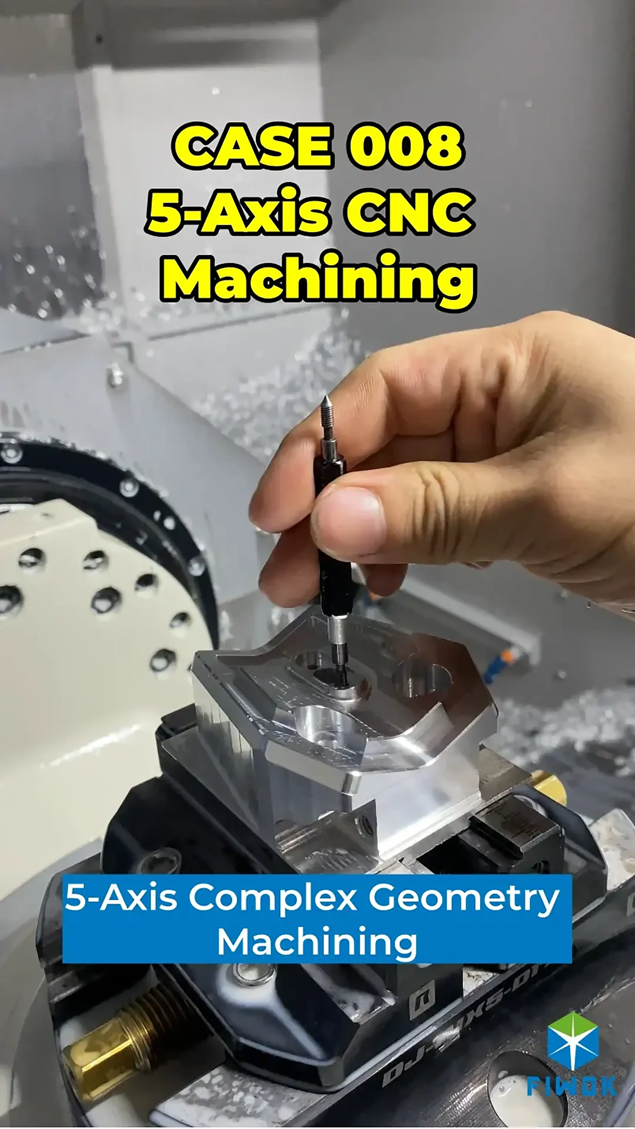
Case 008: 5-Axis CNC Machining of Precision Aluminum Mounting BlockDiscover how our Shenzhen contract engineering team optimized the manufacturing path for a highly complex multi-faceted aluminum block component. By deploying synchronized simultaneous 5-axis CNC machining, we locked in tolerances tightly down to +/-0.01mm, eliminated cumulative positioning errors, and passed direct tiered pricing reductions to the global contract partner.
|
7. Common Machining Issues and Solutions
Aluminum is machinable, but the process still needs control. Common issues should be addressed during programming, fixture design, and process planning:
- Burrs: Reduce tool wear, improve tool sharpness, and plan specialized micro finishing passes.
- Chatter: Shorten tool reach overhang, improve clamping rigidity, and avoid unsupported thin walls features.
- Tool deflection: Use more stable tool geometry factors and reduce unnecessary raw cutting loads.
- Built-up edge: Optimize continuous chip evacuation trajectories and keep cutting oil conditions stable.
- Dimensional drift after finishing: Reserve accurate dimensional allowances before sending lots for bead blasting or coatings.
8. DFM Suggestions for Aluminum Components
Design for Manufacturability (DFM) rules hardware scaling metrics. Leveraging our 14+ years manufacturing database, FIWOK provides comprehensive DFM analysis upon specific request for complex 5-axis component contracts:
- Place tight tolerances (like +/-0.01mm to +/-0.005mm) exclusively on assembly features that truly necessitate them.
- Use realistic rounded internal radii parameters instead of forced sharp inside corners.
- Avoid designing deep narrow pocket geometries unless functionally critical for specialized instrumentation weight metrics.
- Keep active multi-axis tool access trajectories in mind when locating angled side bores and holes.
- Use clear datum references on prints so metrology gating remains reproducible.
- Do not force simultaneous 5-axis link paths if a standard 3-axis or 3+2 indexed tooling setup satisfies the prints.
9. Inspection and Quality Control
A stable aluminum contract machining process must be continuously verified via calibrated equipment, never assumed. Laboratory dimensional inspection is a baseline phase of process tracking control:
- Rigorous First Article Inspection (FAI) validation log tracing to authorize large repeat runs.
- High-accuracy non-contact dimensional profile validation via Shinsein 2D Measuring Projectors 3020.
- Parallelism, flatness, and step limits checking tracked via digital laboratory Swiss DQ V4 Height Gauges and Mitutoyo digital micrometers (0.001mm resolution).
- Calibrated go / no-go pin gauge blocks (0.01mm increments) and threaded steel tracks to secure uniform assembly fits.
- Rigid operational batch inspection routing workflows shared transparently with incoming global contract managers.
5-Axis Aluminum Machining Article FAQ
Q1: What aluminum alloys are commonly used for 5-axis machining?
6061-T6 and 7075-T6 aluminum alloys constitute the global standard choice for precision components. Alloys like 5052 or specialty cast plate stock (MIC-6) are seamlessly integrated depending on structural flat tolerances and chemical surface protection needs.
Q2: Is 5-axis always superior to traditional 3-axis for aluminum components?
No. Extensive blocks or simple hardware brackets are machined more competitively on 3-axis paths. 5-axis centers like our GMU800 or multi-station setups are prioritized when part geometry complexity, extreme undercut profiles, tool access limitations, or radical manual fixture setup changes create genuine production risk reduction.
Q3: What linear dimensional tolerances are realistic for aluminum components?
Linear limits depend heavily on part design thickness, structural wall layouts, material temper choices, and metrology indicators. At FIWOK, custom tolerances from +/-0.01mm down to strict bearing limits at +/-0.005mm are closely controlled using calibrated workshop instruments.
Q4: Why does 5-axis machining significantly benefit scalable batch production?
It drops required physical vice setups and manual repositioning sequences. That reduces location deviation errors, guarantees uniform multi-sided alignment, and keeps execution loops extremely predictable across consecutive manufacturing runs.
Q5: What essential manufacturing documentation must I submit for a quote review?
Please upload your complete 3D digital models (STEP, STP, IGS files) accompanied by detailed 2D PDF drawings highlighting critical linear parameters, thread pitches, surface roughness limits, raw alloy requests, and intended recurring batch quantity scale (10 to 10,000+ pieces).
Q6: How does FIWOK manage tool deflection when machining deep cavities on 5-axis centers?
We maintain extreme rigidity by utilizing hydraulic tool chucks with the shortest possible tool overhang and high-precision variable helix solid carbide tools. Furthermore, synchronous toolaxis tilt programming via our CAM setup permits shorter cutters to cleanly clear complex deep cavities, eliminating tapers or chatter marks.
Request an Engineering Production Quote for 5-Axis Aluminum Components
If your custom aluminum component engineering designs present multi-faceted details, compound angular slots, or recurring contract manufacturing batch size parameters, our multi-axis centers are ready to optimize your supply chain execution. Submit your file set today to receive an immediate technical quotation.
Explore Our Precision Custom Manufacturing Lines